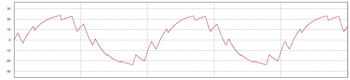
Figure 7 from design and implementation of single phase pure sine wave Inverter circuit sine wave diagram board schematic solar power full electronics projects inverters using 1000w diy 1kw arduino ic 50hz Sine output inverter waveform inverters circuitdigest waves voltage vfd between
Figure 7 from Design and Implementation of Single Phase Pure Sine Wave
Single phase inverter with sine wave pwm Prototype picture of a single-phase sine-wave inverter. Table 1 from design and construction of single phase pure sine wave
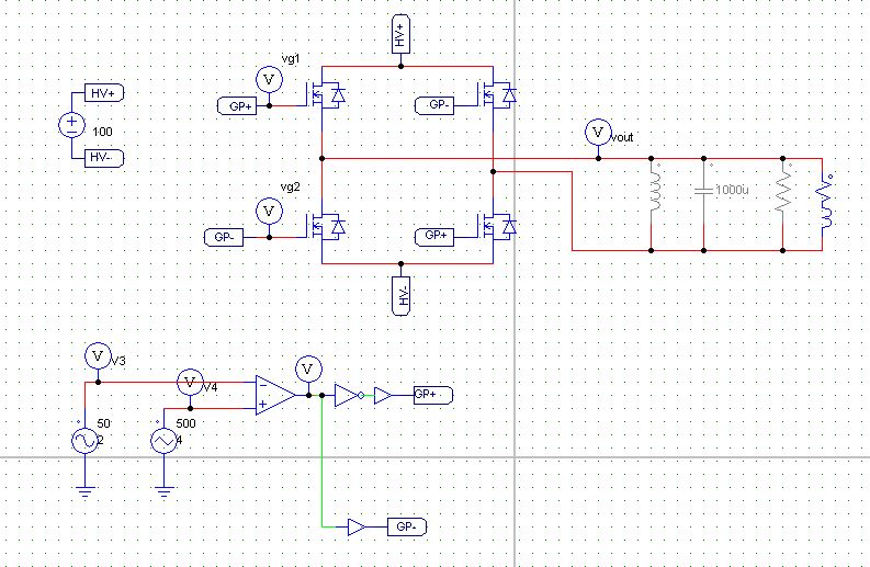
Single phase sine wave inverter with feedback control
Prototype picture of a single-phase sine-wave inverter.Single-phase vs. three-phase: the difference explained! Single phase sine wave inverter equationsSingle phase sine wave inverter equations.
Gating signals and output waveform for pwm sine wave single phaseWhy sine wave is so important when we talk about electrical power? com Sine wave inverter circuit diagram with full explanationSingle phase sine wave inverter equations.

Figure 5 from design and implementation of a pure sine wave single
Solved for the single-phase full-wave inverter shown below,Single phase sine wave inverter equations Block diagram inverter sine wave tym ee mosfetSinusoidal sine waves signals sinusoids conveys.
Phase sine three shift wellpcbSingle phase sine wave pwm inverter Single phase pure sine wave inverter using arduinoSine wave inverter.

Guide complet des schémas de circuits des onduleurs
Single phase sine wave inverter equationsPwm sine waveform inverter phase signals gating pulse modulated Single-phase vs. three-phase: the difference explained!Inverter types & working principle.
Inverter sine arduino microcontrollerslab inspirasi pwmWave sine waveform phase ac single generated generation figure trigonometry Single phase sine wave inverter with only positive interval, becauseWeek-10 challenge: duty cycle : skill-lync.

Figure 1 from design of single phase pure sine wave inverter for
Prototype picture of a single-phase sine-wave inverter.Wave sine sinusoidal waveform two electricity electrical curve Sine wave pure phase inverter singleSine inverter phase circuit principle modified.
Characteristics of sinusoidal signals (sine waves)[pdf] design and implementation of a pure sine wave single phase Design and construction of single phase pure sine wave inverter forDéfinition de l'onde sinusoïdale.

Solved 10. in the single-phase dc-ac inverter simulation,
How a waveform is generated – trigonometry and single phase acPrototype picture of a single-phase sine-wave inverter. processes 2021 Figure 7 from design and implementation of a pure sine wave singleDifference waveform explained.
Sine pure inverter wave implementation multivibrator .


Prototype picture of a single-phase sine-wave inverter. | Download

Figure 7 from Design and Implementation of Single Phase Pure Sine Wave
Single Phase Sine Wave Inverter Equations
Single Phase Sine Wave Inverter Equations

Gating signals and output waveform for PWM sine wave single phase

Figure 7 from Design and Implementation of a Pure Sine Wave Single

Table 1 from Design and construction of single phase pure sine wave